(Updated, Jan 2013, see last section)
Following my earlier post on the matter -published April 9, 2012, I will present now the application of the tachometer for the Raglan Little John Mk.2 Bench Lathe. The application could be quite similar for other lathes, milling machines and machinery in general, which might miss such a digital readout.
Following my earlier post on the matter -published April 9, 2012, I will present now the application of the tachometer for the Raglan Little John Mk.2 Bench Lathe. The application could be quite similar for other lathes, milling machines and machinery in general, which might miss such a digital readout.
Magnet positioning
Choose a lathe part for positioning the magnet and manage to attach it there firmly enough, so that it will not leave its place during revolution. Certain rules of thump should apply for this: (a) the part should revolve at any given state of lathe operation, (b) the revolving part should be immediately related to the lathe spindle, unless tachometer speed corrections are to be involved and (c) magnet should give face to speed sensor, the position of which is an adjoin problem to solve. My selection was to put the magnet on the "outside" looking side of the lathe spindle main gear, as per the following photo.
 |
| 1. Magnet positioning |
First, I cleaned the side, locally and thoroughly, from grease and oil residues using some organic solvent. Then, I prepared a fast setting (4 min) dual component epoxy adhesive mixture, suitable for metals. For this purpose, I used EPOXY STEEL Resin and Hardener Kwik Set of ABRO Industries Inc., PO Box 1174, South Bend, IN 46624, USA (STOCK NO. AB-ES). The set looks like this:
 |
| 2. Dual component epoxy glue (pink -up: hardener, green -down: adhesive resin) |
Please, follow instructions; this set -and many other similar as far as I know- contains hazardous polyamine. I placed a small quantity of the mixture at the back of the magnet and attached the magnet to the side of the gear. I took good care not to attach the magnet too close to the gear circumference, so that to ensure more surface for magnet and gear adherence. Having done this, I engaged the slow gear and tested if there is any interference between the attached magnet and the slow gear pinion; such an interference may forcefully detach the magnet with unwanted consequences.
Speed sensor adjoin problem
The chosen location for the magnet makes it somewhat difficult to find a suitable location for positioning the speed sensor. To overcome the problem I used a piece of 1mm thick polyethylene foil. The foil was cut in a rectangle shape as per the photos,
 | |
| 3. Polyethylene foil with speed sensor attached; view from above (dimensions in mm) |
 |
| 4. Polyethylene foil with speed sensor attached; view from below |
and the sensor was attached to it using straps, through two 4mm diameter drill holes. Some approximate dimensional details (in mm) can be observed on the photos (especially if you zoom them). Exact dimensions for your Little John may vary a bit, mostly due to differences in castings and the like. Material had to be removed from some parts of the foil, so that to allow for its optimum positioning with regard to other lathe parts involved. To understand why, take a look at the next photos, 5 and 6, depicting the foil with the sensor at its final position.
 | |
| 5. Polyethylene foil with sensor in place (a) |
 |
| 6. Polyethylene foil with sensor in place (b): note the appropriate distance between the sensor and the magnet |
The large drill hole (10mm actually) has been made to permit bolting the lathe headstock top cover. Bolting the headstock ensures and stabilizes the position of the foil as well. Some material removal around the foil central part was needed for giving access to the spindle oiling channel of the headstock rear bearing. Some material removed at the left part of the foil ensures that the side (left) cover for the gear train will fit into position without meeting any foil obstacle. It is obvious that the set-up as designed and implemented allows for fine tuning positioning of the speed sensor relative to the magnet, if and when necessary. Lucky me, the heads of the straps, as used to fasten the speed sensor onto the foil, seem to support it as well on the upper surface of the bearing housing. Find out how, at this picture:
 |
| 7. The strap heads support the foil on the bearing housing |
The speed sensor is connected to the cycle computer with a thin signal cable. One has to ensure that the cable will not mess with the gear system, else it will be destroyed. My arrangement of choice, is already shown in picture 7. See also below that some straps secure the thin cable at its place.
 |
| 8. Secure thin cable in place using a strap |
 |
| 9. Thin cable secured and side cover of gear train in place |
I have put the cycle computer screen on the speed adjustment lever, which, in case of this particular lathe has been disengaged from its original function, since mainly for ease of maintenance the Continuous Variable Transmission system was replaced by a classic pulley array.
 |
| 10. The cycle computer in idle, just showing time (18:36) |
Programming of the cycle computer was made as per the instructions at the theory post of April 9, 2012. The photo below shows the result on the cycle computer screen, when the lathe runs at ~425 rpm.
 |
| 11. The cycle computer in operation as tachometer indicates 425 rpm |
Note, that it takes some time (let's say 5-10 secs) for the cycle computer to read correctly the spindle speed, and that radio frequencies in the neighborhood may prevent it from operating correctly.The whole installation adds some minor complexity, when there is a need for uncovering the headstock.
That's all (1)!
Verification (January 2013)
Following some limited feedback that I received for the above mentioned application, I managed to verify the cycle computer indications using an analog industrial revolution meter by SMITH's Industrial Division. This meter, with serial LO382, is in fact a collector's item of the 60's coming straight out of the engine room of merchant shipping of that era. The meter was kindly provided by colleague Mechanical Engineer A. Nikoglou. Below find the meter's photo. It looks much better if you download the photo and take a look at it in enhanced resolution.
To use the meter, lathe chuck was removed and the face plate was adjusted on the spindle. A dead center was also placed into the spindle's MT4 hollow cone. First, lathe was turned on in "forward" motion and then the revolution rate was measured using the information coming from the dead center, as per the setup in the following picture.
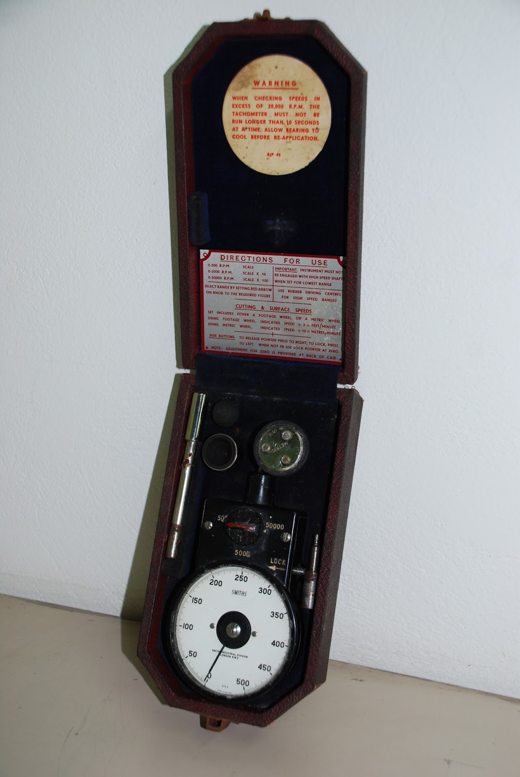 |
| 12. SMITH's Industrial Division revolution meter (ca. 1960) |
To use the meter, lathe chuck was removed and the face plate was adjusted on the spindle. A dead center was also placed into the spindle's MT4 hollow cone. First, lathe was turned on in "forward" motion and then the revolution rate was measured using the information coming from the dead center, as per the setup in the following picture.
 | |||
| 13. SMITH's revolution meter in action: setup "1" |
It is worthy to note that both the cycle computer and the revolution meter demonstrate very similar speeds, if one takes some time to compare photo 11 with photo 13. Subsequently, the revolution rate was also measured using the information coming from the circumference of the face plate, as per the setup in the following picture.
 |
| 14. SMITH's revolution meter in action: setup "2" |
In metric, and according to the manual of the instrument, the above indication means 200 meters per min at the face plate circumference. Given that the radius of the face plate is 3" or 76.2 mm or 0.0762 m, then the radial speed of the spindle is 200/0.0762 = 2624.67 rad per min. Therefore, the rpm of the spindle can be calculated as 2624.67/(2π) = 418 rpm. Consequently, and once more, the cycle computer and the revolution meter demonstrate very similar
speeds, if one takes some time to compare photo 11 with photo 14, taking into consideration the above calculations.
All photos of this section were taken by fellow engineer A. Nikoglou.
I now call this post verified, and let you be.
That's all (2)!
Rights and citations
Copyleft
protects this post. This means that you may freely copy and distribute
this content but please do not change it. If you, in the process, find
that something in this post is inappropriate or wrong, please contact me
at my e-mail. I would be more than happy to update the post. You are
more than welcome to site this post in your own texts, blogs or
whatever. If this is the case, please use more-or-less the following
citation format:
Petropoulos, N.P., "Raglan Little John Mk.2 Bench Lathe - Post 3 - Tachometer (application)", 2012; add URL; add access date.
Any citation will be much appreciated.
Rights and citations
Petropoulos, N.P., "Raglan Little John Mk.2 Bench Lathe - Post 3 - Tachometer (application)", 2012; add URL; add access date.
Any citation will be much appreciated.