1. Introduction
The travelling steady (or in other wording the follower rest) is usually optional equipment for the bench lathes. However, the follower rest could be proven quite handy for specific projects even for the bench lathe, especially in cases of processing long, thin and light materials. Given that nor RAGLAN neither their successors at MYFORD are in business any more, follower rests (or any rests for that matter) for Raglan Little Johns are nowadays quite rare, so -in case of need- one might have to construct his own or adapt one available from the market. For our situation, it was decided that it is worthy to give it a go with the second choice, since the machining capacity in the little shop is somewhat limited. In this post, I will try and review in detail a serial process of fitting the alien follower rest to our Little John, productively and efficiently. The whole project is estimated to cost approximately something like 50,00 EUR or about so and no more than 5 to 6 hours of work at a quite relaxed pace. The necessary tooling and materials are: drill press, hand drill, twisted drills of various diameters, M6x1.0 taps, M6x1.0x20 mm allen bolts (hex socket and countersunk socket heads), files, a hacksaw, angle grinder (maybe) and, of course, the follow rest to be adapted. A mill drill or even a milling machine is desirable, if available, but not really necessary.
2. Looking for the suitable follower rest in the market
The bench lathe accessories available in the market, are predominately Chinese made. For this project one should look for accessories of well-known quality, suitable for bench lathes with similar dimensions to these of the Little John. In my point of view, such bench lathes could be -among others, the Optimum Maschinen GmbH types D240x550/D250x550 and the Model C6 Mini Lathe, now (2013) known as the Super C6 lathe. Both lathes have a "swing over bed" capacity of 250 mm much similar to the Little John's 10". To my best of understanding these two lathes share common components, which have been designed by the same team and/or are probably manufactured in the same Chinese facilities. Here are the respective pictures of the follower rests available for these lathes:
(a) For the Optimum D240x550/D250x550 and according to their catalog:
 |
| Fig. 1 Follower rest for the Optimum bench lathe |
For the lathes in question a(max.)=34 mm; b=220 mm; c=107 mm.
(b) For the Model C6 (or Super C6) Mini Lathe:
 |
| Fig. 2 Follower rest for the Super C6 Mini Lathe |
For this rest a(max.)=21 mm, no other dimensions are specified.
Such rests when in work, look like this:
Following the particulars of the Greek market, it was much easier to obtain the first follower rest (part number 3441310).
 |
| Fig. 3 Follower rests of type (a) or (b) in work |
3. Modifying the selected rest
Having in mind what the follower rest's job is, its suggested position relative to the cutting tool and the available space and other particulars of the Little John lathe, it was decided to remove (literally cut off) the selected rest's base. This can be achieved by using the hack saw or the angle grinder. In the latter method, please use eye and hand protection and do not apply excessive force since the rest's profile has thin parts susceptible to breakage; nevertheless, in our case the hack saw was preferred. Here is a series of pictures presenting this project stage in steps:
 |
| Fig. 4 The follower rest before any intervention |
 |
| Fig. 5 The follower rest without base (it looks kind of amputated, doesn't it?) |
 |
| Fig. 6 The follower rest on the mill to make the remaining base face horizontal and perpendicular to the sides |
 |
| Fig. 7 Front view of the follower rest on the mill before milling |
 |
| Fig. 8 Front view of the follower rest on the mill after milling; base surface is set |
4. Preparing for the fitting
Having done the initial modification of the rest, it was time to find out what is the rest's center height in relation to the lathe centers. To this end the tailstock and a kit of 3mm thick parallel plates were used. Here is how it looked:
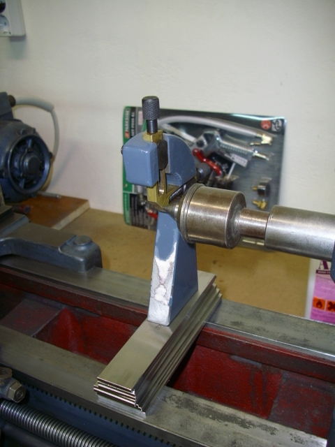 |
| Fig. 9 Rest's center height in relation to the lathe centers |
It was found that approximately 25 mm (8 parallels) should be added over the lathe's bed surface so that the center of the rest could acceptably level with the axis of the lathe. With this information in hand, the following DIN 1017 steel flatbar ("b" wide" by "s" thick) pieces were purchased:
(1) b=70 mm, s=20 mm of length=130 mm, and
(2) b=25 mm, s=25 mm of length=115 mm
Piece (1) was selected to be 70mm wide, since the distance between the bed ways bases on the Little John is something like 72-73 mm depending on the base cast roughness. This piece, as it will be shown, is meant to be positioned between the bed ways and permanently attached underneath the saddle of the lathe, exactly under the cross-slide.
Piece (2) was selected to be 115mm long, since the distance between the front saddle (above the carriage apron) and the back saddle (above the rear bed way) on the Little John, is approximately 120 mm. This piece, as it will be shown, is meant to be positioned between the saddles.
5. Actual fitting
 |
| Fig. 10 Tool post compound temporarily removed |
Secondly, since piece (1) is to be attached underneath the cross-slide, the cross-slide bottom face had to be investigated in terms of roughness, parallelism etc. Hand feeling the surface revealed number "70" embedded on the surface during casting. This number is the part number of the saddle cast as found in Little John's Mk2 Operator's Handbook, page 27. The following image speaks for itself:
 | ||
| Fig. 11 A view of the saddle bottom |
To secure piece (1) positioning at the saddle bottom somewhat parallel to the cross-side surfaces, piece (1) can be given some specific machining to allow for a pocket big enough for these two numbers, or the numbers can be filed off, if you do not mind too much messing with the originality of the saddle cast. The socket machined in this case, looked like this:
 |
| Fig. 12 Machined pocket in piece (1) to allow its attachment to the saddle bottom without interference from cast lettering |
After this machining and/or filing, piece (1) was temporarily positioned underneath the saddle as per the following two images:
 |
| Fig. 13 Piece (1) temporarily positioned, view from the right |
 |
| Fig. 14 Piece (1) temporarily positioned, view from the left |
Note the ~0.8 mm thick aluminum foils placed between the piece and the lathe bed sides in ALL four corners. These foils should be always LOOSE, during this procedure and also after finalizing the positioning of this piece. This precaution would allow for the necessary clearance between piece (1) and the Little John's internal bed side faces and, in turn, this clearance would permit the unhindered sliding of the carriage, as it had been before this modification.
With piece (1) temporarily attached, the way described, a hand motor drill was used to prepare the saddle for this simple attachment. The plan was to bolt piece (1) to the saddle with two allen M6x1.0x20 mm bolts of the countersunk socket type. Both saddle and piece (1) were drilled at the same time. However, holes on piece (1) were only initiated by the drill. Piece (1) drill holes were finalized at the drill press with a 5 mm drill and hand-tapped to M6 thread. Here are images after this step:
 |
| Fig. 15 Saddle drilled; small diameter is 6 mm |
 |
| Fig. 16 Test positioning of the allen bolts |
Another necessary precaution at this stage was to be sure that the bolts heads would not interfere with the tool compound bronze nut at any circumstances. Consequently, some further filing was necessary:
 |
| Fig. 17 Filing some material off the tool compound bronze nut |
Following the filing:
 |
| Fig. 18 Adequate clearance between the nut and the allen heads obviously established |
And after this, piece (1) could be bolted, in order to further proceed.
 |
| Fig. 19 Piece (1) bolted into position; carriage moves as smoothly as it used to |
Piece (2) was positioned on piece (1) and follow rest was positioned on piece (2), so that some first tests of the final arrangement could be made.
 |
| Fig. 20 First look of test arrangement seemed more than satisfying |
 | ||
| Fig. 21 Marking |
Using a thin marker like the one, one uses to write on a CD/DVD two lines were drawn on the horizontal face of piece (2).
The one nearest to the center marks where the front edge of the follow rest base should be placed, so that the center of the rest is approximately on the lathe axis. This line is further extended downwards on piece (2) and piece (1) left side faces. Aligning the vertical lines on these side faces secured repositioning piece (2) on piece (1) in the same position, if and when piece (2) had to be removed for machining.
The other line on the horizontal face of piece (2) indicates the cross-section of piece (2) which is aligned to the front face of piece (1) looking towards the bed way internal face.
These two lines on the horizontal face of piece (2) indicate the free space within which bolts can be applied to attach piece (2) to piece (1). After some bench and drill press work on piece (2), things looked like that:
 |
| Fig. 22 Piece (2) made ready with through holes for M6x1.0x20 mm allen bolts (hex socket); view 1 |
 |
| Fig. 23 Piece (2) made ready with through holes for M6x1.0x20 mm allen bolts (hex socket); view 1 |
At this stage piece (1) was marked respectively for these two holes with a 6mm drill. Then it was removed once more and the respective drill holes were finalized at the drill press with a 5 mm drill and hand-tapped to M6 thread. After this, piece (1) was again put into place for further processing. Piece (2) bolted on piece (1) looked like this:
 |
| Fig. 24 Piece (2) bolted on piece (1) |
A further marking line can be seen near the back edge of the horizontal face of piece (2). This line along with the one nearest to the center as introduced earlier in Fig.21, indicate the space within which, bolts can be applied to attach piece (2) to the follow rest . From this point on, bench and drill press work was necessary on piece (2) and the follow rest. Some photos follow:
 |
| Fig. 25 The follow rest on the drill press; holes are marked |
 |
| Fig. 26 The follow rest on the drill press; 5mm holes are on the make |
Note, once more the wooden splint precaution taken to support the thin part of the rest's profile from breaking, due to possible drilling excessive forces.
 | |
| Fig. 27 Hand-tapping M6 threads in blind holes (fingers were crossed) |
Piece (2) bolted to the travelling steady:
 |
| Fig. 28 Finished follow rest bottom view |
And finally, the finished follow rest was ready to be fitted on the lathe:
 |
| Fig. 29 The finished follow rest |
Everything was disassembled and thoroughly cleaned. It was decided that tightening the bolts might not be enough in the trembling lathe environment, therefore, bolts, which are not meant to be removed from this point and on were further secured using a product similar to LOCTITE 222:
 |
| Fig. 30 Securing the bolts on the follow rest |
 |
| Fig. 31 Securing the bolts on piece (1) |
The tool post compound was put back in its place:
 |
| Fig. 32 Follow rest with tool post compound in place |
Some preparations for the final painting:
 |
| Fig. 33 Primer painting before final |
 |
| Fig. 34 Modified follow rest hand painted but still looking quite sharp |
 |
| Fig. 35 Modified saddle with piece (1); allen bolts threaded in place for safe keeping |
Views of the follow rest in place for work:
 |
| Fig. 36 The follow rest in place for work (view 1) |
 |
| Fig. 37 The follow rest in place for work (view 2) |
6. Some remarks
Original Little John's travelling steadies are certainly rare; their pictures are rare as well. In order to present an idea how the original steady looked like here is a poor image scavenged out from the Owner's Handbook page 31:
 |
| Fig. 38 Little John's original travelling steady |
Also, here is an image found on the net:
 |
| Fig. 39 Little John's original travelling steady with its older bro the fixed steady |
These two images can give an idea on how the original could be placed and work on the tool compound. It is worthy to note that the modification presented herein, attaches the steady to the saddle and not the compound, something that might be proven handy at times.
Some other relevant images can be also found in the RaglanMachineTools Yahoo Group (in http://groups.yahoo.com/groups/RaglanMachineTools).
I had recently a personal communication with this Yahoo Group moderator Mr. John Burridge (John.Burridge@fsmail.net). He let me know that he has been making steadies for the Raglan lathes, both fixed and travelling and also an extended fixed steady of 150mm capacity (6"). He has the drawings and he can get castings of them, which in turn can be machined and finished.
The construction presented, however, although interesting and maybe productive, is not flawless. It seems that chips could be grabbed between piece (1) and the bed sides making the carriage movement troublesome. Nevertheless, for the light work on synthetics, bronze and aluminum, for which the Little John lathe is used in our premises, this should not be a problem.
7. Rights and citations
Copyleft
protects this post. This means that you may freely copy and distribute
this content but please do not change it. If you, in the process, find
that something in this post is inappropriate or wrong, please contact me
at my e-mail. I would be more than happy to update the post. You are
more than welcome to site this post in your own texts, blogs or
whatever. If this is the case, please use more-or-less the following
citation format:
Petropoulos, N.P., "Raglan Little John Mk.2 Bench Lathe - Post 5 - Fitting an alien follow rest (travelling steady)", 2013; add URL; add access date.
Any citation will be much appreciated.
7. Rights and citations
Petropoulos, N.P., "Raglan Little John Mk.2 Bench Lathe - Post 5 - Fitting an alien follow rest (travelling steady)", 2013; add URL; add access date.
Any citation will be much appreciated.